Computer Networking From The First Principles : From Electricity To The Internet
Back in the day, sending a message from point A to point B relied entirely on humans or animals. Not only was it slow, but it was also unreliable. Messages could get lost, delayed, or even misinterpreted. And the farther the distance, the bigger the problem. Imagine having to travel across the world just to deliver a single message. It sounds crazy, but this was reality for a long time.
Then humans invented telegraph lines, one of the first forms of electronic communication. Suddenly, messages could travel almost instantly across large distances. It was not perfect. But it was a huge leap forward from relying on messengers.
As technology advanced, we eventually built computers, machines that could store, process, and manipulate information at incredible speeds. This opened up a whole new world of possibilities. What if two computers could communicate directly with each other, reliably, and almost instantly? This question became the foundation of modern networking.
Please note that this is a high-level overview, and I might skip concepts that are not relevant for this blog.
By the way, if you’d rather watch than read, I’ve made a video on this too.
Representation of Information as Numbers
Before we even talk about computers communicating, we need to understand one thing: how computers represent information internally.
Any kind of information - text, images, videos, anything - is ultimately stored as physical states. In digital systems, those states are usually voltages. The voltage ranges are defined so that the system can interpret them as either 1 or 0. For example, a voltage greater than a certain threshold (say, 5 volts) could be considered 1, and anything lower could be 0. We just need a clear distinction. That’s what base 2 really is: information represented in two stable physical states.
In RAM, these bits are stored as tiny electrical charges inside capacitors. If the capacitor holds charge, it’s a 1; if it’s empty, it’s a 0. But since that charge leaks over time, the system constantly refreshes it, which is why it’s called dynamic memory.
In contrast, hard drives store data magnetically. Each tiny region on the disk’s surface can be magnetized in one direction or the opposite. For example, north can represent 1 and south can represent 0. So instead of holding charge, it holds magnetic orientation, which stays even when the power is off.
So at the most fundamental level,it’s just about reading two physical states: charge or no charge, north or south etc. Everything else is built on top of that.
But how do we represent more complex things like numbers, text, or even images using just 1s and 0s?
Encoding Text
Encoding is the process of mapping real-world information into numbers. Let’s start from first principles.
Suppose we agree that:
- a = 1
- b = 2
- c = 3
- d = 4, and so on.
Now, if someone sends the numbers 5 12 14, and we both know this mapping, we can decode it as letters e l n. Those numbers now carry meaning because we agreed on a shared mapping.
That is the essence of encoding: creating a consistent rule to turn ideas into numbers so both sides can understand them. Computers do the same thing but at a much larger scale.
The earliest standardized mapping for text was ASCII, which assigns a number to each letter and symbol. Later, UTF-8 came along to handle all languages and emojis by using multiple bytes when needed.
So when you write “hello” on your computer, what’s actually stored is:
01101000 01100101 01101100 01101100 01101111
That’s the binary form of UTF-8 encoded text.
Encoding Images and Color
Now, what about images? Images are just grids of pixels, and each pixel is represented by numbers too.
Before that, let’s understand something fundamental: color is not a property of an object. It’s a perception created in your brain based on how light of different wavelengths hits your eyes.
Your eyes have three types of cone cells - S (short), M (medium), and L (long) - that respond to different ranges of light wavelengths. Roughly, S detects bluish light, M detects greenish light, and L detects reddish light. Because our vision system relies on three types of signals, we can recreate nearly all visible colors by mixing just three components: Red, Green, and Blue (RGB).
Each pixel on your screen uses this RGB model. For example:
- Pure red might be (255, 0, 0)
- Pure green (0, 255, 0)
- Pure blue (0, 0, 255)
- Yellow is (255, 255, 0) - a mix of red and green
Every pixel in an image is just a triplet of numbers (R, G, B), and the entire image is a grid (or matrix) of such numbers. So an image can be thought of as a giant 3D array of numbers.
Just like we represented letters as numbers earlier, we represent colors using numeric values too. And just like the decimal number system that uses digits 0-9, the binary system uses only 0 and 1 to represent all those values inside the computer.
Connecting Two Computers
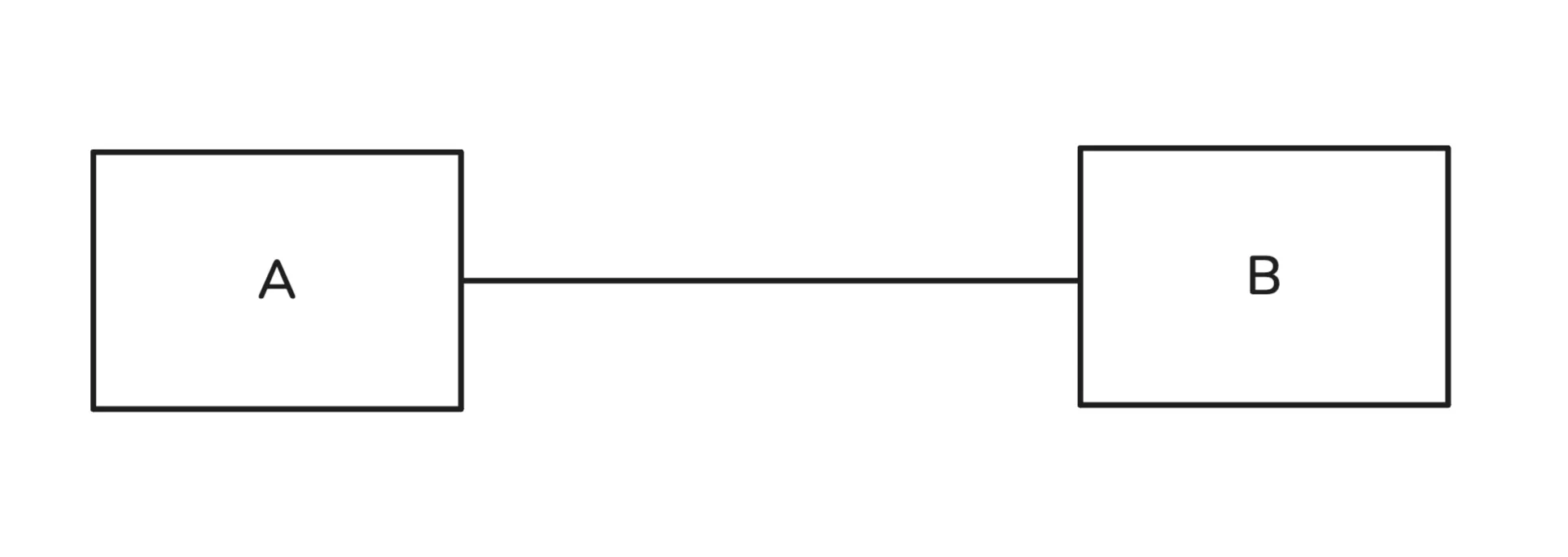
If we want to share information between just two computers, we can connect them using a wire, such as a copper cable, and transmit data in the form of voltage levels.
For example, to transmit 1011, this could look something like this : apply +5V on the wire for a sec, apply 0V for a sec, apply +5V for a sec and +5V again for a sec. Another computer will also check for voltage levels every sec.
Every bit is considered a timed event. Both computers can agree on a transmission speed, say 10,000 bits per second. The receiving end then checks for a bit every 1/10,000 of a second. This way, information can be shared reliably between two computers.
There are still some challenges. For instance, the receiving computer doesn’t know what kind of file was sent, so it may not know how to interpret the data. It also needs to agree on how frequently to check for each bit. We’ll come back to these issues later. For now, the important point is that we can send and receive information between two computers.
Connecting 100 Computers
This was straightforward for two computers, but what if we had 100 computers and wanted to share information between any two of them? The brute force approach would be to connect each computer directly to every other computer.
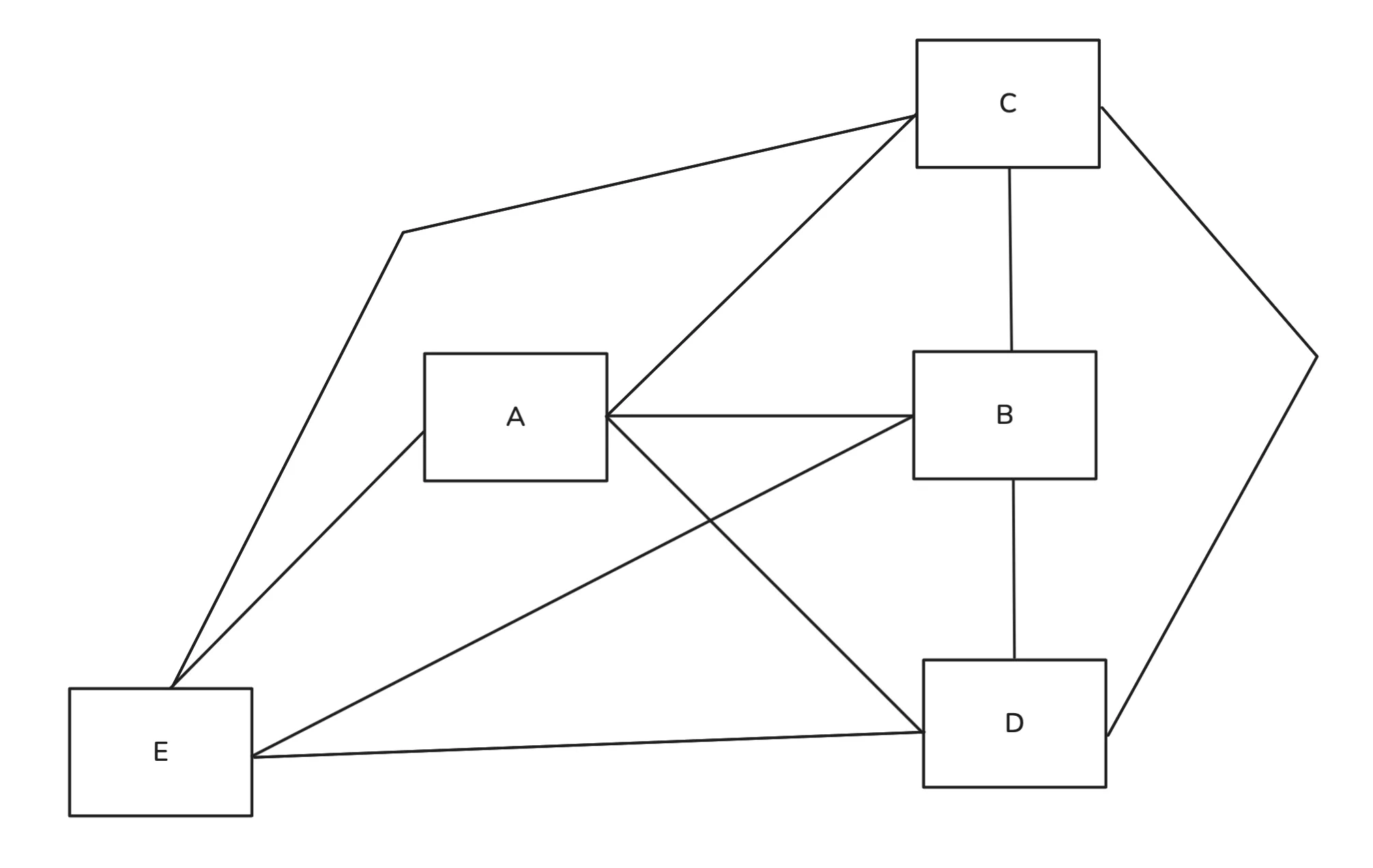
For 100 devices, each computer would need 99 input/output ports. This is clearly impractical. There has to be a better way.
Switch
We developed a new device that connects to every computer, receives binary data, and forwards it to the correct destination. Let’s call it a switch. Before we understand how it works, you should know that each device has a unique MAC address burned into a hardware component, usually the network interface card (NIC). We can take advantage of this unique identifier.
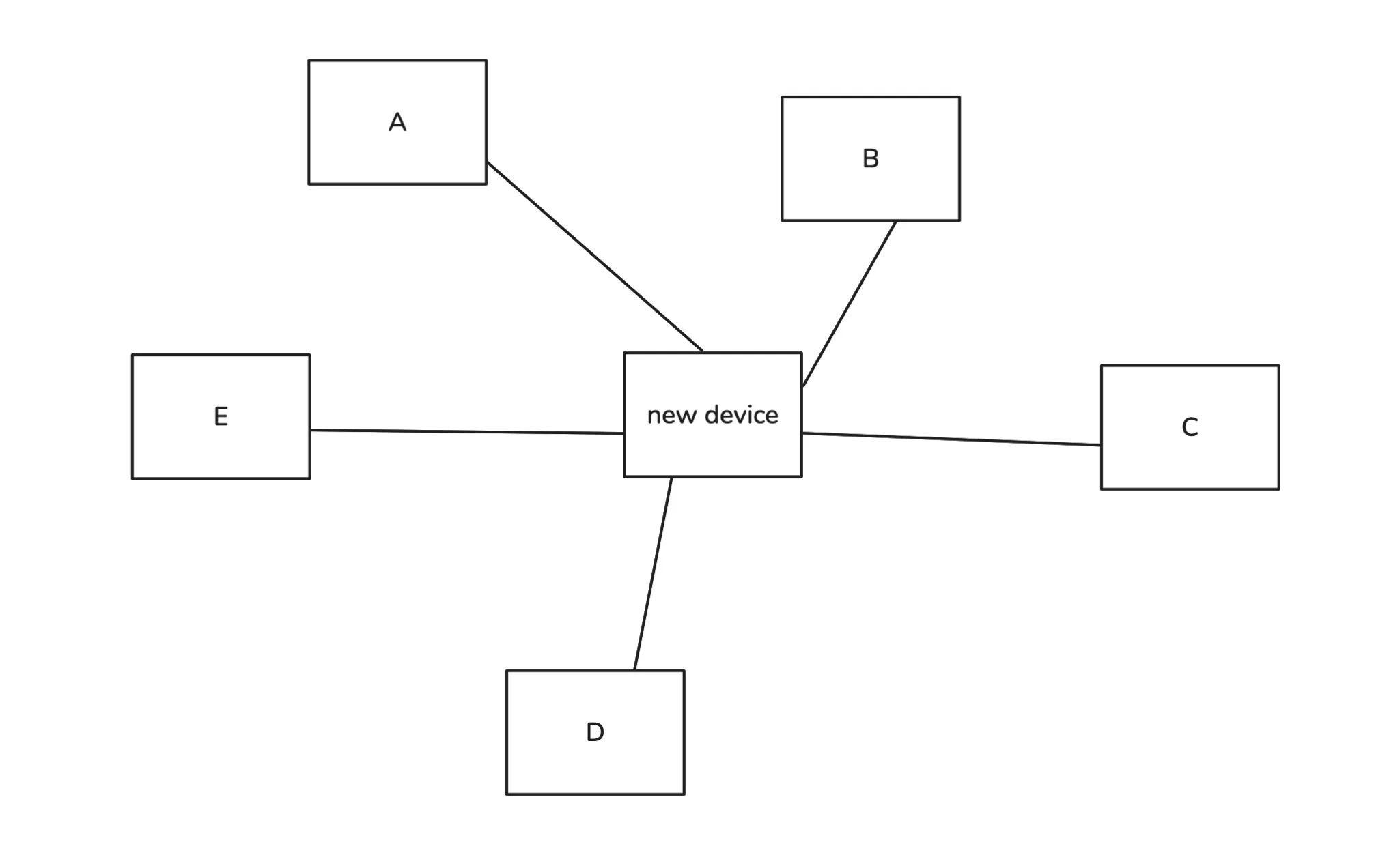
Suppose computer A wants to send data to computer C. If we send the bits directly to the switch, it won’t know which computer should receive them. To solve this, we add additional information specifying the source and destination MAC addresses. In reality, there is also other control information, but we will ignore that for now.
But where do we add this information? At the start of the data, at the end, or somewhere else? This is exactly why we have protocols. Without them, every switch might expect a different structure, and nothing would work consistently.
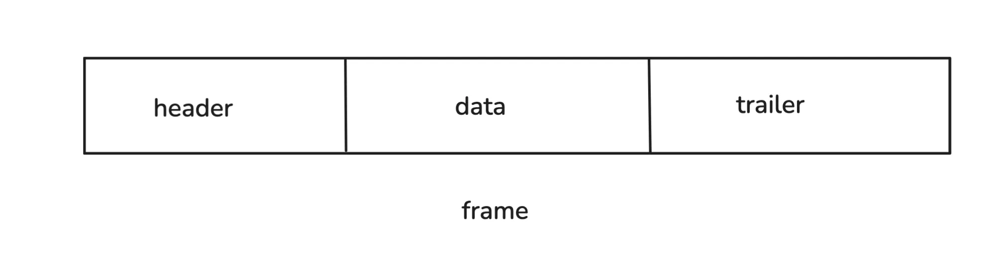
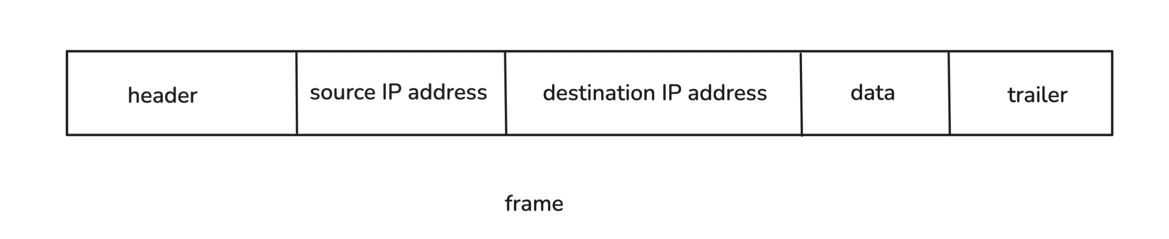
The defined structure is called a frame. The header part stores the source and destination MAC addresses. The data part contains the sequence of bits we want to transmit, and the trailer contains some information for error checking.
So instead of sending raw bits like 1001010 in sequence, we add bits at the start and end that tell the switch where the data should go. The switch reads the frame, decodes the destination MAC address, and forwards the data to the correct computer, using its MAC address table.
Connecting 1 Million Computers
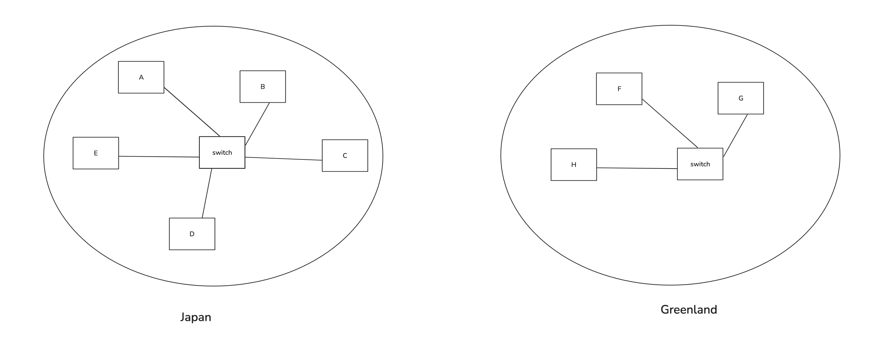
Now suppose there are some computers in Japan and some in Greenland, and we want them to communicate. Say, A wants to send data to F. A simple approach would be to connect both switches using some physical medium.
When A sends data with the destination MAC address of G, and the switch doesn’t know which port to use, it floods every connected device with the message and waits for a response. So it floods B, C, D, E, and the other switch. Now, that switch may also not know where F is, so it floods G, H, and F. When F replies, the second switch notes down F’s MAC address and the port it’s reachable on, then forwards the response back. The first switch also updates its MAC table, mapping F’s address to a port.
You see the problem? If there were a billion such networks, every switch would flood constantly, wasting bandwidth. Plus, devices can change networks, making old entries invalid. Switches work fine for small local networks, but we need something smarter for large-scale communication. And there’s another issue: communication still depends on knowing the MAC address of the destination.
We need a more scalable system.
A new way of address - IP Address
What’s the core problem here?
We’re identifying devices purely by flat MAC addresses. There’s no sense of where a device exists in the global structure. To fix that, we need a hierarchical addressing system.
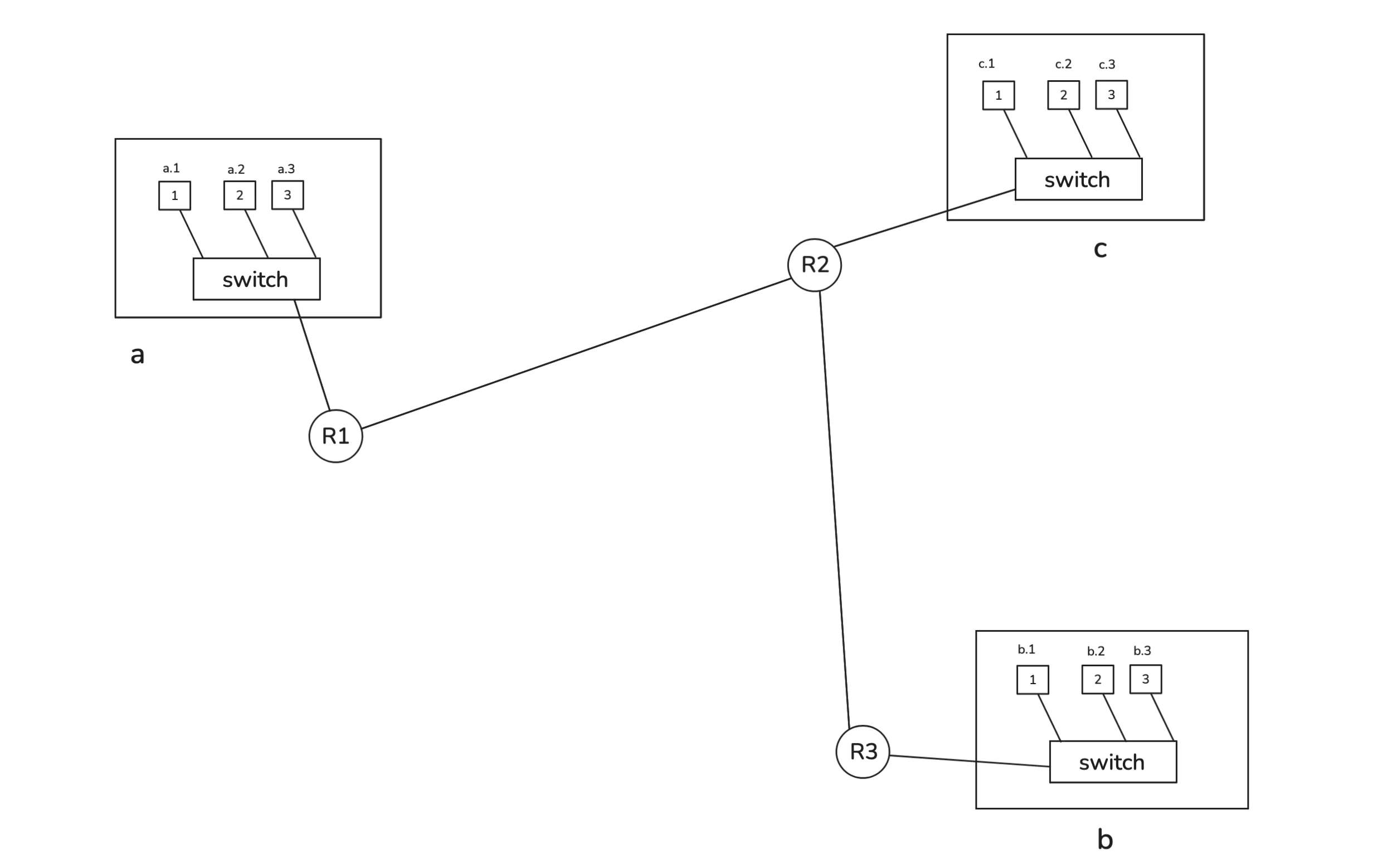
Imagine dividing networks into groups. Let’s label them A, B, C, … Z, and then naming individual devices inside them like A.1, A.2, B.3, C.4, and so on.
Now, if you want to reach C.3, the device or switch can instantly know that it needs to route the data toward network “C” rather than searching blindly through every connected machine.
But switches can’t handle this logic. They only work with MAC addresses. We need a new kind of device that understands this hierarchical addressing and can route data between different networks.
That’s where the router comes in. It assigns, compares, and forwards data based on these higher-level addresses which call IP Addresses.
Routers
The router itself also has a MAC address (so switches can still talk to it).
Say your computer has an address like A.4 and you want to reach B.3. Your system knows that B.3 is not part of the local network (because A.something and B.something belong to different network), so it sets the destination MAC address of the router instead. The router receives this frame, unwraps it, and looks inside for the IP address information to figure out what to do next.
A switch expects this kind of frame format:
So, we add source and destination IP addresses inside the data part before the switch wraps it with Ethernet headers. We’re just adding some extra bits to our data we need to transmit. Think of it as more metadata. The router unwraps the frame, checks the IP information, and forwards it accordingly.
It looks something like this:
When a router receives a frame, it checks its routing table. It is a kind of internal map that tells it which networks are reachable through which interfaces. Routers share this information with each other regularly. For example, they keep sending the routing details for each network accessible to them every 30 sec.
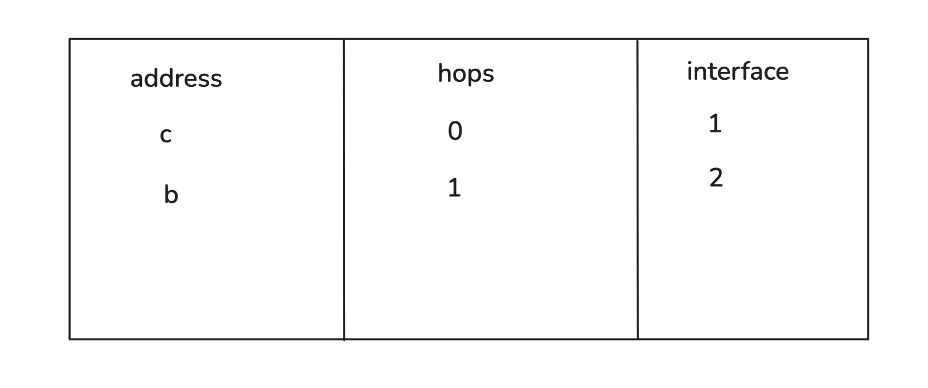
So, the router might see that to reach network “B,” it needs to forward the packet through interface 2. It rewrites the Ethernet header (new source and destination MACs) and forwards it to the next router. Eventually, when it reaches the destination network, the final router recognizes the IP address as local(destination IP is B.3 and the router is also connected to network B so we call it local) and sends the frame directly to the correct device.
If A wanted to reach A.2 instead, it would perform an ARP (Address Resolution Protocol) request to find the MAC address of A.2 and send it through the switch.
Our earlier naming scheme (A, B, C …) was just an analogy. In real systems, IP addresses use numerical formats like IPv4 (e.g., 192.168.1.1) and IPv6 for the modern internet, which allows trillions of devices.
Sending 1 GB File (Need For Packets)
There’s an issue with the way we’re sending our data. Suppose we want to send a 1 GB video file. What are we gonna do? There are gonna be 8e+9 bits (1s and 0s) in a sequence, along with some file headers. Then, we’re gonna put the source IP and destination IP in front of it, and finally wrap it with an Ethernet header and trailer. The source and destination MAC addresses will be present in the header.
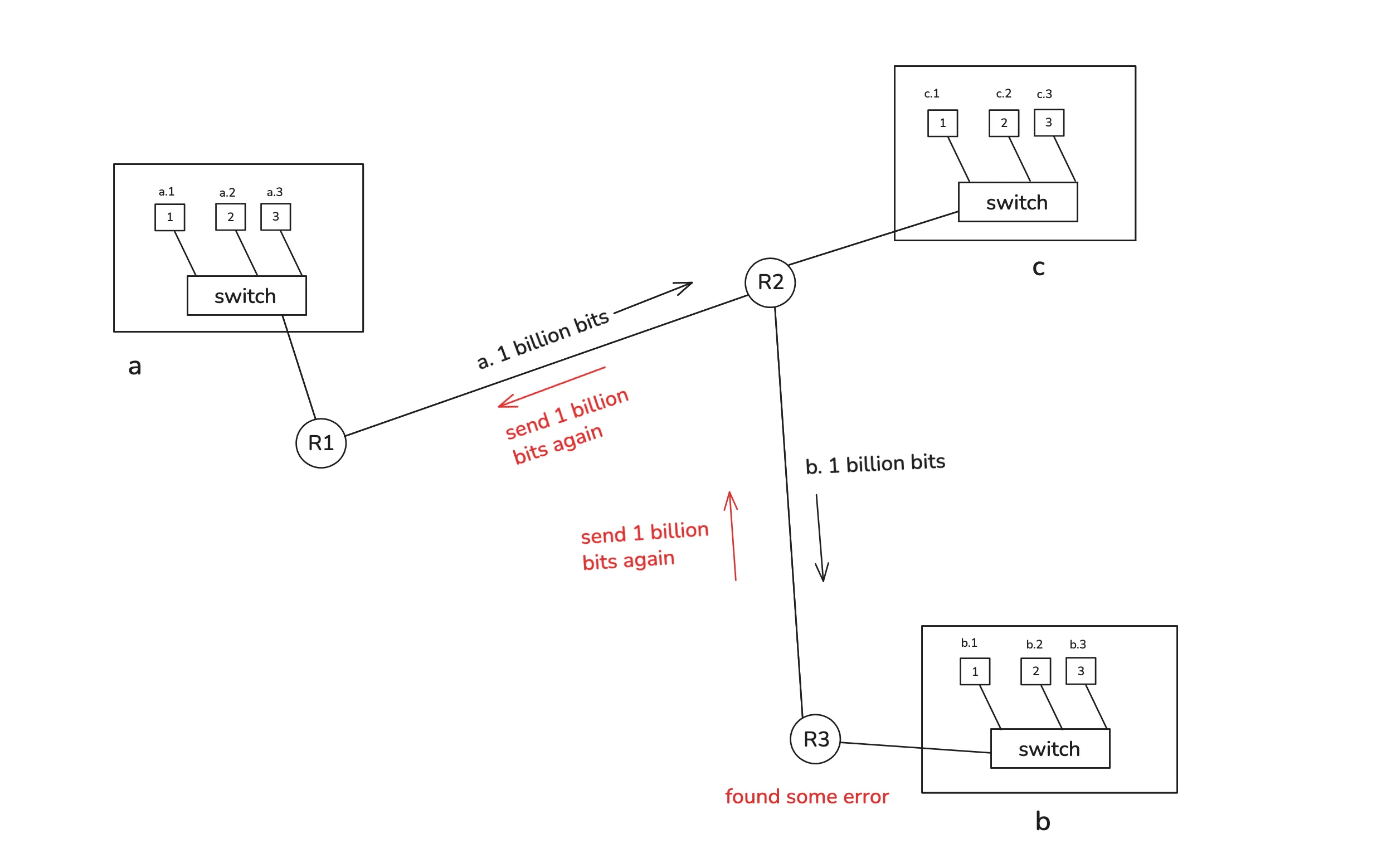
Say it’s destined for B.4. First, we’re gonna send those bits to the router C and then to B. Suppose C received all of them. Then it’s gonna start sending them to B. But what if a bit was flipped while transmitting? There are some methods we can use to detect whether we received the expected bits. Now B has to ask for the bits again. C is already done with the transmission, so it has to ask for them again from A. You see the problem? A 1 GB file again if there’s some error? That makes no sense.
Another problem is that it’s gonna hog the transmission line for you. We’ll talk about frequency channels later, but for this setup, others would have to wait for it to finish.
We’re gonna follow a new strategy. Instead of sending 8e+9 bits all at once, we’re gonna send them in chunks. Say we select the first 1500 bytes, create a frame according to the protocol, and send it. Then we select the next 1500 bytes, create a frame, and send that. But how is the receiver gonna know how to arrange them? So, we add a new field called a sequence number, which tells the position of the bytes so it’s easy to join them on the receiver’s end.
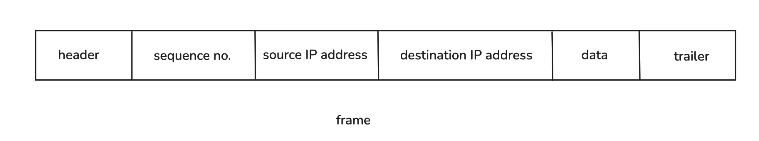
This whole frame is constructed step by step. First, we get the data and then wrap it up with the source IP, destination IP, and sequence number. What we have till now is called a packet (the sequence number is part of the transport layer, but we’ll ignore that for now). Then some Ethernet headers and trailers are added. Once we have that, we call it a frame. These are just terminologies, nothing more. At the end, we’re still sending binary data.
Now, if there’s some error during binary transmission, it can ask for that specific frame with a sequence number instead of asking for the whole file again. And other people can also send data at the same time. Say I send packet no. 1, then maybe someone else sends packet no. 4, then I send packets 2 and 3, and they send packets 5 and 6. This can go on. It’s fair for everyone.
Data Type - text, image, or something else?
So far, everything we’ve sent is binary data. But what does that binary actually represent? Is it text, an image, or a video? The receiving system needs to know how to interpret it.
Suppose our data is 01101000 01100101 01111001. What does that even mean for the receiver?
Is it text saying “hey”? Is it part of an image? Or maybe HTML code for a webpage?
The receiver has no idea what this binary sequence represents unless we tell it how to interpret it.
So what do we do? We define a protocol, or more precisely, several of them, that describe the rules for sending and interpreting different kinds of data. These are called application-level protocols, such as HTTP, FTP, SMTP, and many others.
That’s where application-level protocols come in, which are things like HTTP, FTP, SMTP, and so on.
Understanding the “Why”
At lower layers like Ethernet, IP, and TCP, everything is just bits being transmitted. But at the application layer, we finally care about the meaning of those bits. This is where context enters. The same binary sequence could mean completely different things depending on the protocol being followed.
For example, suppose I want to request my notes from another computer. In UTF-8 encoding, the text “notes” translates to:
01101110 01101111 01110100 01100101 01110011
I could send this binary directly, but the other computer would have no idea what to do with it. So, we use a protocol that defines how such a request should look and how it should be interpreted.
Example : HTTP
For web communication, the standard protocol is HTTP (HyperText Transfer Protocol). So I can send something like this:
GET /notes HTTP/1.1
Host: www.shekhardangi.tech
User-Agent: Mozilla/5.0
Accept: text/html
Here’s what each part means:
- GET /notes asks the server for the resource named /notes.
- Host: specifies the server’s domain name.
- User-Agent: identifies the client, such as a browser.
- Accept: tells the server what kind of content the client can handle, like HTML or JSON.
On the server side, there might be code saying: “When a request comes for /notes, send back the notes file.”
The server then responds like this:
HTTP/1.1 200 OK
Content-Type: text/html
Content-Length: {length}
{body}
The browser reads these headers, sees that the content type is HTML, and displays it properly.
Notice how the format is consistent. If someone wrote HTTPPPP/1.1 200 OK instead, the browser would not understand it because that version does not exist in the protocol definition.
Example : SMTP
Now, consider how email works. It uses another protocol called SMTP (Simple Mail Transfer Protocol). Here’s an example message:
HELO mail.example.com
MAIL FROM:<alice@example.com>
RCPT TO:<bob@example.com>
DATA
Subject: Hello
Hey bro,
Did you get this?
.
QUIT
This format too follows a strict set of rules so that any mail server in the world can understand and process it.
Finally, all this text is still converted into binary before being sent. The encoding method, like UTF-8, converts characters into sequences of 1s and 0s. Then each protocol layer adds its own headers and trailers, wrapping the data in TCP segments, IP packets, and Ethernet frames until it can travel through physical media.
The Final Picture : OS, NIC, and other components
Now let’s connect everything.
First, you decide what data you want to send, and then some application constructs it according to a specific protocol. For example, your web browser might construct a message like this:
GET /notes HTTP/1.1
Host: www.shekhardangi.tech
User-Agent: Mozilla/5.0
Accept: text/html
This request is then encoded into binary data using an encoding scheme such as UTF-8. Now you have raw binary data ready to transmit.
Your browser then asks the Operating System (OS), or more precisely the kernel, to send this data to a particular IP address. You don’t manually handle things like sequence numbers, source and destination ports, or IP addresses. That’s all managed by the OS.
The Role of the Operating System
The operating system is essentially the bridge between your applications and the hardware. It provides controlled access to CPU, memory, and devices, ensuring one program doesn’t interfere with another.
For example:
- Need to access memory? You ask the OS.
- Want to start a new process? You ask the OS.
Without this control, any random program could read other apps’ data or hog CPU time.
So, when your browser gives the binary data to the OS, it’s written into kernel memory, which is a protected space that user applications cannot access directly.
Once the OS has the data, it breaks it into smaller chunks and adds TCP or UDP headers containing information like:
- Sequence number (for ordering packets)
- Acknowledgment number (for confirming received data)
- Source and destination ports
- Checksums and flags for control
Now the OS knows your IP address, so it wraps each chunk in an IP header, adding both the source and destination IP addresses. At this point, what you have is an IP packet.
The OS also maintains its own routing table, just like routers do. It decides whether the packet should go to the local machine (localhost), to another system on the local network, or to the default gateway (the router).
NIC
Next, the Network Interface Card (NIC) steps in. The NIC has Direct Memory Access (DMA), which means it can directly read the kernel’s memory without bothering the CPU. It takes those IP packets and wraps them in Ethernet headers that include:
- Source MAC address
- Destination MAC address
- Error-checking information
Now the data is ready for physical transmission.
If you are connected via Ethernet, the NIC converts the binary data into electrical signals. Like flipping between voltage levels like 0V and 5V to represent bits.
If you are on Wi-Fi, the NIC instead converts those bits into radio waves.
Modulation
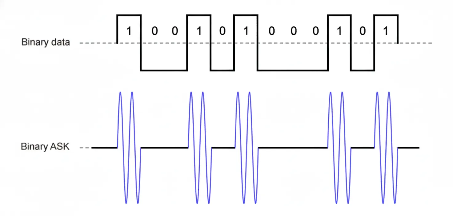
How do we use radio waves to represent bits? Through a process called modulation. It is a way of mapping digital information onto an analog wave. There are several types of modulation:
- Amplitude Modulation (AM) – varies the wave’s height (amplitude)
- Frequency Modulation (FM) – varies how fast the wave oscillates
- Phase Modulation (PM) – shifts the wave’s starting point (phase)
For example, in Amplitude Modulation, a higher amplitude might represent a binary 1, and a lower amplitude a 0.
Routers, Modems, and Signal Conversion
Once the router receives the signal, it may need to forward it to your ISP or another router further along the path until it reaches the destination.
Sometimes, the next link might not use radio at all. It could be fiber optic cables that transmit data using light pulses. The router, however, has received electrical or radio signals, not light. That’s where the modem comes in.
The modem (short for modulator-demodulator) converts the incoming signal into the correct physical form expected by the next device. For example, turning electrical signals into light for fiber transmission or vice versa.
Every layer adds meaning and structure, transforming your “message” into a precise, physical phenomenon that travels across the world and gets interpreted correctly on the other side.